Monday, April 26, 2010

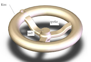
Solidworks video tutorial about how to Apply solidworks simulation stress analysis tool to Hand wheel


solidworks simulation  is a first pass stress analysis tool for SolidWorks users. It helps you judge whether your part will withstand the loading it will receive under real-world conditions according to factor of safety. 

Overview

COSMOSXpress uses a wizard to provide an easy to use, step by-step method of performing design analysis. The wizard requires several pieces of information in order to analyze the part: materials, restraints and loads. This information represents the part as it is used. For example, consider whathappens when you turn the handwheel. The hub is attached to something that resists turning. This is represented by a restraint - the hub is restrained so it doesn’t move. A force is applied to the hole in the rim as you attempt to turn the handwheel. This is a load. What happens to the spokes? Do they bend? Will they break? This depends on the strength of the material the hand wheel is made of, the physical size and shape of the spokes, and the size of the load.

Mesh

In order to analyze the model, COSMOSXpress automatically meshes the model, breaking it up into smaller, easier-to-analyze pieces. These pieces are called elements.

Although you never see the elements, you can set the coarseness of the mesh prior to the analysis.

Results

The analysis produces results in the forms of Factor of Safety, Stress Distribution and Deformed Shape.

Using the Wizard

The design analysis wizard walks you through the steps of analysis, from Options to Results. The steps are:

  • Options
Setup the type of units that are commonly used for materials, loads and results.

  • Material
Choose a material for the part from the standard library or input your own.

  • Restraint
Select faces of the part that remain in place (fixed) during the analysis. These are sometime called constraints.

  • Load
Add external loads such as forces and pressures to induce stress and to deform the part.


  • Analyze
Run the analysis, optionally setting the coarseness of the mesh used.

  • Results
View the results of the analysis: Factor of Safety (FOS), Stress and Deformations. This is sometimes called postprocessing.


Saturday, April 17, 2010

Hand wheel Design tutorial based on Revolved features


These solidworks tutorials about Revolved features throw hand wheel Design Hand wheel divided in to 3 solids the hub and Rim connecting with third solid The spokes


Hub dimension (mm)


Rim dimension (mm)
spoke dimension(mm)


Saturday, April 10, 2010

solidworks tutorials Mirror and Pattern


In this solidworks tutorial  you will learn 


how to make Mirror and Pattern for solidworks part

linear and curved pattern for 3d model part


Monday, March 22, 2010

Make 2D drawing from solidworks part

4.1 This solidworks tutorial about 2D
Drawing  (Idler Arm) from 3D model learn :

 How to change view and take cross section of 3D model and 2D drawing ? 

 How to edit color and martial  of  3d model ?

Deal with drawings and annotations categories and know

 How to make a basic 2D drawing from 3d model  part?

How to choose your layout sheet (A4,A5,.......etc)?

How to put your dimensions in drawing ?

How to make drawing details ?

free solidworks tutorials


2D layout

 
(4.1)


(4.2)

 
(4.3)


(4.4)

Friday, March 12, 2010

3D modeling of idler arm step by step video tutorial


 3.1 This solidworks tutorial about Features toolbar
Drawing  (Idler Arm) and learn

How to edit feature edit sketch ? 

How to make Extruded boss Up To surface ,select contours ?

Why merge result  ?

How to make extruded cut and extruded cut up to surface?

Make constant radius fillet


 idler arm 3D model


 (Idler Arm)

Solidworks 3D model Video tutorial for idler arm part


Saturday, March 6, 2010

2.2 SolidWorks Sketching tools

2.2 In this solidworks tutorial learn 

how to make your first sketch using sketch tools?

how to make sketch relations?

how to put smart dimensioning on skitch?

Make your first extrude from sketch (know the different between blind and mid plan extrude)


Thursday, March 4, 2010

2.1 Sketching


2.1 In this solidworks tutorial  you will learn How to deal with solidworks sketch tool bar (line,circle,rectangle, smart dimension and sketch relations)


Sunday, February 28, 2010

Thursday, February 18, 2010

Solidworks Space

A bout Solidworks cad cam program space i collect for you  SolidWorks Tutorials (3d model , cosmos analysis) and also you could watch new designs, 3d model, and drawings  by solidworks professionals and locale like me you will learn all solidworks basics also find guidelines for your solidworks certifications.

Wednesday, February 17, 2010

CSWA Guidelines

 CSWA


As a Certified SolidWorks Associate CSWA, you will stand out from the crowd in today’s competitive job market. CSWA certification is proof of your SolidWorks® expertise – cutting-edge skills that businesses seek out and reward.

Recommended Self-paced training: SolidWorks Tutorials
Exam Length: 3 hours
Minimum Passing grade: 70%
All candidates receive electronic certifcates and personal listing on the CSWA directory* when they pass.
Exam features hands-on challenges in many of these areas:
  • Sketch entities - lines, rectangles, circles, arcs, ellipses, centerlines
  • Sketch tools - offset, convert, trim
  • Sketch relations
  • Boss and cut features - extrudes, revolves, sweeps, lofts
  • Fillets and chamfers
  • Linear, circular and fill patterns
  • Dimensions
  • Feature conditions – start and end
  • Mass properties
  • Materials
  • Inserting components
  • Standard mates - coincident, parallel, perpendicular, tangent, concentric, distance, angle
  • Reference geometry – planes, axis, mate references
  • Drawing sheets and views
  • Dimensions and model items
  • Annotations
  • SimulationXpress

*This option must be set in your online certification account to show up in the directory
**Login required for access. Full access requires an active Subscription Service contract

*** source www.solidworks.com

How to Design a Boat Hull in SolidWorks


Tuesday, February 16, 2010

solidworks software

3 Type
according to: tools and features
  • SolidWorks Standard
  • SolidWorks Pro
  • SolidWorks Premium

SolidWorks standard

The SolidWorks cad software  includes tools for 3D modeling ,  assembly, 2D drawings , sheetmetal, weldments, and free form surfacing. easy drafting  It can import numerous file types from other 2D and 3D Model cad software like autocad . It also has an API for custom programming in Visual Basic, C++, C#, and other COM-compliant languages. Also included is an entry level finite element analysis program called SolidWorks SimulationXpress (formerly known as CosmosXpress) like ansys.

SolidWorks Professional

The SolidWorks Pro bundle includes the SolidWorks core product plus several add-in programs. These include:
  • Design Checker (Checks notes, dimensions and other settings in drawings to make sure they adhere to company standards)
  • eDrawings Professional (Adds markup and measuring capabilities to the free eDrawings viewer)
  • FeatureWorks (Adds editable features to "dumb" imported geometry)
  • Pdmworks (A workgroup level document management program to manage SolidWorks files as well as other file types)
  • PhotoWorks (Realistic Photo rendering)
  • Task Scheduler (Schedule SolidWorks to bulk print, import/export files, and create eDrawings)
  • Toolbox (A collection of common fasteners and hardware, Screws, Nuts, Washers, etc.)
  • Utilities (Additional tools for selecting features and comparing features and geometry)
  • 3D Instant Website (Publishing an HTML document of SolidWorks documents, uses eDrawings for viewing)

solidworks tools

 SolidWorks Flow Simulation

SolidWorks Flow Simulation is a Computational Fluid Dynamics (CFD)  modling  product for SolidWorks users. It is embedded inside SolidWorks and can perform fluid flow and heat transfer analysis for some types of fluids (liquids, gases, Non Newtonian fluids, Compressible liquids).
The solver uses Navier-Stokes (NS) equations to compute flow characteristics in both Single Reference Frames (SRF) and Multiple Reference Frames (MRF).
SolidWorks Flow Simulation has its solver and part of components from FloEFD of Mentor Graphics. Despite SolidWorks Corporation does not publish details of the models and meshing technology, the Mentor Graphics does. This is extremely important to CFD engineers understand the limitations and applicability of the software.

 SolidWorks FloXpress

SolidWorks FloXpress is a free, limited-scope version of SolidWorks Flow Simulation now included in every seat of SolidWorks, starting in 2008. It can handle only internal flows with one inlet and one outlet, of either air or water. Only velocity traces are given as results, no heat transfers are calculated. It should be considered an initial validation tool only, for the casual FEA user.

SolidWorks Sustainability

New in solidworks 2010 , SolidWorks Sustainability measures the environmental impact over the life cycle of the product in terms of  four factors: carbon footprint, air acidification, water eutrophication, and total energy consumed. For each of these, the dashboard displays current value, a baseline comparison to the design and percent contribution.

 SolidWorks Motion

SolidWorks Motion is a SolidWorks module for multi-body kinematic simulation of mechanisms. It can handle complex component collisions, accept formula for motion laws and supply reaction values to SolidWorks Simulation for further FEA analysis. It is included in the SolidWorks Premium license.

 SolidWorks SimulationXpress

SolidWorks SimulationXpress (formerly COSMOSXpress) is a feature designed to perform a limited range of linear static analysis of part geometry. Geometry is limited to a single solid body and the choices for creating boundary conditions are limited (fixed only) which can affect the applicability of the results to the actual problem being solved. Results are limited to graphical representations of either Von Mises stress or displacement distributions. Colors appearing on the surface of the deformed shape of the model describe the amount of stress or displacement at that location. The values corresponding to each color are shown in the legend. SolidWorks SimulationXpress is included in every basic SolidWorks license, and should be considered a first-pass check to see where a design can be improved.

SolidWorks Simulation Premium

SolidWorks Simulation Premium is a module providing a richer set of tools for linear static FEA. SolidWorks Simulation Premium can deal with parts and assemblies using solid, shell and (starting from release 2007) beam elements.
It provides a fully associative environment to perform FEA studies inside SolidWorks, with several features for pre-processing as well as for post-processing and a very rich set of connectors and boundary conditions, like virtual bolts, bearings, spot welding, links and pins.
A tool for designing multiple batch calculations (Design Scenario) is also provided.
SolidWorks Simulation Premium can handle locally non-linear contact and includes a partial support for geometric non-linear analysis (large displacement). It is included in the SolidWorks Premium license.

solidworks file format

SolidWorks files use the Microsoft Structured storage file format. This means that there are various files embedded within each SLDDRW (drawing files), SLDPRT (part files), SLDASM (assembly files) file, including preview bitmaps and metadata sub-files. Various third-party tools (see Structured storage) can be used to extract these sub-files, although the subfiles in many cases use proprietary binary file formats.
Solidworks 2010 SP0.0 opens/saves following file formats: SolidWorks Files (*.sldprt, *.sldasm, *slddrw), Part Files (*.prt, *.sldprt), Assembly Files (*.asm, *.sldasm), Drawing Files (*.drw, *.slddrw), DXF (*.dxf), DWG (*.dwg), Adobe Photoshop Files (*.psd), Adobe Illustrator Files (*.ai), Lib Feat Part (*.lfp, *sldlfp), Template (*.prtdot, *.asmdot, *.drwdot), Parasolid (*.x_t, *.x_b, *.smt_txt, *xmt_bin), IGES (*.igs, *.iges), STEP AP203/214 (*.step, *.stp), ACIS (*.sat), VDAFS (*.vda), VRML (*.wrl), STL (*.stl), Catia Graphics (*.cgr), ProEngineer Part (*.prt, *.prt.*, *.xpr), ProEngineer Assembly (*.asm, *.asm.*, *.xas), UGII (*.prt), Autodesk Inventor Part (*.ipt), Autodesk Assembly (*.iam), Solid Edge Part (*.par, *.psm), Solid Edge Assembly (*.asm), CADKEY (*.prt, *.ckd), Ass-ins (*.dll), IDF (*.emn, *.brd, *.bdf, *idb).

Solidworks V8 Engine

Formula 1 racing parts designed in SolidWorks


Tools Download

Download new versions and Service Packs for SolidWorks, Simulation, PDM, 3DVIA products, and Free CAD Tools (eDrawings, DWG Navigator, DWG Gateway, Drawings Now, SolidWorks Explorer).
Download

Monday, February 15, 2010

SolidWorks Sheet Metal Part Models From Solid Body

SolidWorks 2009 introduced more than 250 time-saving enhancements. Here, we spotlight one of our favorite new features: the ability to transform a solid body into a sheet metal part. Follow the step-by-step directions below to get started.
Step 1: Creating the solid body shape
Model the sheet metal part you wish to create as a solid body shape. Think of this as a frame for your part to wrap around. Start thinking about where the bends and rips need to be positioned.
Step 2: Converting the solid body shape into a sheet metal part
On the Command Manager bar, select the "Sheet Metal" tab.
Click on the "Convert to Sheet Metal" button.
Step 3: Adjusting conversion settings
Within the sidebar section you will see several options:
Under "Sheet Metal Parameters," select the face to fix, and then adjust thickness and radius settings for the metal.
Under "Bend Edges," choose edges where it will bend, starting with edges adjacent to the fixed face you chose.
Under "Rip Edges found," SolidWorks displays automatically selected edges to rip.
Under "Rip Sketches," you can manually add rips by sketching on any face.
Under "Auto Relief," specify the type and ratio for relief.
Step 4: Changing rip or bend values
Within the main window, you will see each rip and bend has a box linked to it. These boxes designate the gap for rips, or the radius for bends. This matches the default value that you set initially, but you can change any of them as needed.
Step 5: View your creation
Un-suppress the Flat Pattern feature to view the part in flattened state. Check for errors and congratulate yourself on a job well done.
This new functionality makes creating a sheet metal part easier than ever. Try it today and discover how much time and effort you can save.
Want to learn more about SolidWorks sheet metal capabilities?
Ask the experts at EngATech, your source for SolidWorks 3D CAD software, CAD training, support, and product design services.

Article Source: http://EzineArticles.com/?expert=Emily_Poindexter

Solidworks Masters

When it comes to mechanical computer aided design cad software , SolidWorks is quickly becoming the industry leader. You may already be familiar with the basics of Solidworks, but how do you become a master of this high tech tool? SolidWorks provides a powerful set of engineering design tools to design products better no matter what size your business is. While the software is technically amazing in that it allows you to design and test virtual prototypes of any imaginable device, learning how to use it is no small achievement.
To get the most out of SolidWorks, you need to be extremely familiar with the program. This includes all of the many nooks and crannies as well as add-on programs. The key to honing your SolidWorks skills is practice and training. The better you understand the program, the more efficient and productive you'll be at design. Here are eight tips to improve your design skills and help you become a master SolidWorks user:
1. Formal Training. One of the best ways to get started with a new software program is taking a formal class. In a classroom you'll get invaluable hands on instruction from a Solidworks professional instructor. You'll be committed to showing up and learning, plus the peer pressure of the other students will motivate you to put in the extra effort that would likely not occur if teaching yourself.
2. Non-traditional training. There are numerous online training materials and books if you prefer to be "home-schooled". You can learn at your own pace, but must be motivated enough to keep at it. Just Google Solidworks training and you'll see tons of third-party training videos, books, etc.
3. Value Added Resellers (VARs). You can often find special events for new users from your local SolidWorks VAR. VARs often offer seminars or night schools where you can find out more about SolidWorks.
4. User Groups. In order to stay current and network with other SolidWorks users, joining a user group is a great idea. It's typically free to join and you can learn technical tips from other users. Search for a user group near you at http://www.swugn.org.
5. Be a Superuser. Become the go-to person at your company - the SolidWorks guru. Let other users come to you with their questions and problems. Considering yourself to be an expert will motivate you to learn more.
6. Discussion Forums. Getting involved in a discussion forum is a great way to get help or submit advice based on your previous experience. Solidworks maintains one of the best at forum.solidworks.com.
7. CSWP Test. The Certified SolidWorks Professional exam provides a standard measure of SolidWorks competency. You'll feel confident in your skills and be recognized by employers as a certified user.
8. Create CAD Standards. To ensure productivity in SolidWorks, create a CAD standard book. Document how to begin new parts and drawings, how to handle design revisions, how you manage standard parts, and so on.
The best approach to mastering SolidWorks is to mix and match several of the eight techniques listed above. As the saying goes practice makes perfect. Each year there are new releases, so you'll want to stay current with new features of the software.